ASTM D5762
Standard Test Method for Detection of Nitrogen in Petroleum and Petroleum Products by Boat-Inlet Chemiluminescence
“D5762 is the preferred method for the quantitative determination of trace nitrogen in hydrocarbon samples. The controlled and complete combustion of the sample convert all organically bound nitrogen compounds in nitrogen oxide. The method takes advantage that NO reacts quantitatively and very fast with O3 forming an excited NO2* that luminesces in the Red/NIR region releasing an amount of energy proportional to the N concentration that is captured by a PMT set at the appropriate wave lengths region. The N-detector response is equimolar and linear with a vast dynamic range.
The advantages of this method over other spectroscopic and chemical methods are based on the speed of the analysis, the reduction of matrix effects, the selectivity of the chemiluminescence reaction, the high precision and accuracy and the selectivity of the determination.
Nitrogen is hardly found in fuels and petroleum products quality specifications however its determination is gaining importance due to several factors: It degrades the activity of expensive catalysts especially platinum based ones used in conversion processes like reforming and isomerization. Also, N at low concentrations competes with S in HDS processes making hard to achieve the desired desulfurization degree. Although N is not a finished luboil specification, the N content can be used as a quality control parameter in the final formulation.” (Aaron Mendez Ph.D.)
Method Summary:
For the detection of nitrogen using ASTM D5762, a weighed quantity of the hydrocarbon sample is placed in a sample boat at room temperature and mechanically driven into a high-temperature pyrotube in a rich oxygen atmosphere, where all the N-compounds are oxydized to nitric oxide (NO). the analyzer at a controlled speed into the vaporization and combustion zones of the instrument. In the inlet zone the sample is transported by an inert stream of a carrier gas, typically Argon or Helium. The hydrocarbon is oxidized in a rich pure oxygen stream in the combustion zone at approximately 1000°C where it is converted into CO2, NO and H2O. Water interferes with the signal and causes instability of the base line, so after the gases exit the combustion zone they are passed through a semipermeable Nafion® membrane where the water is quantitatively removed. The dried gases pass through a Mo convertor where NO2 molecules in case they form will be reduced to NO to enhance the detector signal.
The gases enter the Nitrogen reaction chamber where they are mixed with a stream of O3 to produce an excited NO2* species. The NO2* molecules upon relaxation release an amount of energy proportional to the N original concentration. The relaxation takes a few nanoseconds and the energy captured by a properly set Photo Multiplier Tube, is amplified processed and recorded. The signal obtained is proportional to the total nitrogen content of the original sample.
Significance and Use
Nitrogen compounds are not the most abundant heterocompounds in hydrocarbon streams. However, they also poison catalysts in refinery processes and they are very difficult to get rid of, in part due to the different polarities they exhibit going from acidic to amphoteric in behavior. In hydrotreating processes they compete with sulfur degrading the efficiency of hydrodesulfurization to reach very low levels of sulfur in gasoline and other fuels.
Apparatus
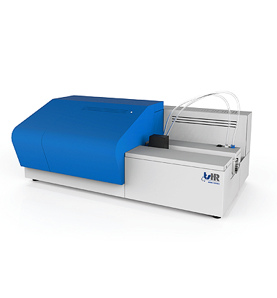
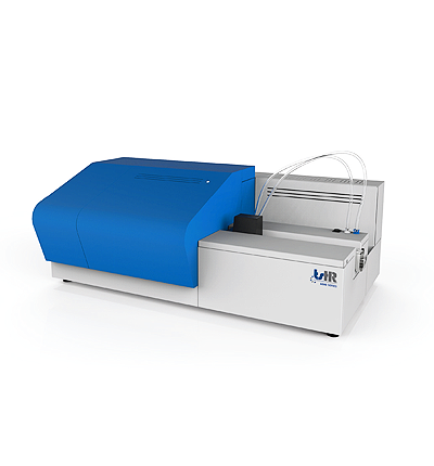
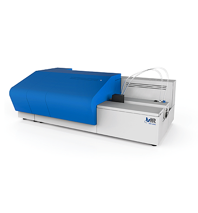
The analyzer of horizontal configuration for low or non-volatile organic liquid and solid compounds is represented in fig.1. The system can also be provided with an automatic sample changer for the syringe introduction of volatile liquids as well. The inlet and furnace are differentially heated and divided in three regions. The inlet section is heated high enough to facilitate the vaporization of the sample and is mainly contacted by the stream of the carrier gas typically Argon that transport the gases into the other sections of the furnace where the combustion process takes place.
Combustion Tube, they vary in design and dimension entirely depending on the manufacturer’s criteria for optimization of the combustion characteristics and sample transport efficiency. In general, they should be large enough to accept the sample boat and have side arms for the introduction of the combustion and carrier gases. There other pyrotubes available that contain a spiral inner tube for a secondary stream of oxygen or Turbo oxygen added in the hottest furnace zone to guarantee the combustion of the most refractory species and to add extra residence time for their combustion. Uncombusted hydrocarbon species in general quench the detectors signals and degrade the sensitivity of the instruments. 
Test Procedure:
Apparatus preparation and calibration: Once the system has been assembled, leak tested, heated and stabilized per the instrument manufacturer, typical operating conditions are stablished and adjusted as per the manufacturer’s guidelines. The fact that the fundamental characteristics of equimolarity and linear response of the technique causes that any organic compound containing at least one bound atom of N can serve as a calibration compound and the calibration can proceed with a minimum of three points. Based on anticipated nitrogen concentrations needs the instrument is then calibrated either by dilution of a stock solution or using a calibration kit from commercial standard reference laboratories. Set the calibration method to average three consecutive injections for each calibration point. Check the linear regression coefficient of the obtained calibration curve and make the necessary corrections should the linearity not be in accordance with D5762 and the manufacturer’s instructions ( R2 ≥ 0.999 or 1 to 2 orders of magnitude for the calibration range). It is a good laboratory practice to start the calibration in ascending order to reduce risk of carryover that could affect the linearity of the calibration and the results of the ASTM D5762 detection of nitrogen test.