ASTM D6371-17a
Standard Test Method for Cold Filter Plugging Point (CFPP) of Diesel and Heating Fuels
Standard test method D6371 covers the determination of the Cold Filter Plugging Point (CFPP) in Diesel and Heating Fuels in either instrument versions, manual or automated. Both methods are considered to be referee methods in case of any technical disagreements.
D6371 can be applied to distillate fuels containing flow-improving or any other additives normally intended for diesel engines or domestic heating oil installations.
In D6371 the fuel is cooled by immersion in a constant temperature bath to make the cooling step a nonlinear process but certainly a faster one of approximately 40 °C per hour. In general, CFPP is the temperature of the sample being analyzed when 20 mL of it first fails to pass through a standard wire mesh in less than 60 s.
This international standard was developed in accordance with internationally recognized principles on standardization established in the Decision on Principles for the Development of International Standards, Guides and Recommendations issued by the World Trade Organization Technical Barriers to Trade (TBT) Committee.
Crystals of sufficient dimensions and quantities can plug filters used in fuel systems and other parts of machinery and also cause operational problems in crude oil and petroleum products blending operations. A precise and reliable determination of these properties and of the ability of petroleum oils and other products to flow freely constitutes a valuable tool not only to more precisely determine the specifications of new products but also to monitor important handling, transport and processing operations.
Referenced Documents
ASTM Standards:
D2500 Test Method for Cloud Point of Petroleum Products and Liquid Fuels
D4057 Practice for Manual Sampling of Petroleum and Petroleum Products
D4177 Practice for Automatic Sampling of Petroleum and Petroleum Products
D5771 Test Method for Cloud Point of Petroleum Products and Liquid Fuels (Optical Detection Stepped Cooling Method)
D5772 Test Method for Cloud Point of Petroleum Products and Liquid Fuels (Linear Cooling Rate Method)
D6371 Test Method for Cold Filter Plugging Point of Diesel and Heating Fuels
D7962 Practice for Determination of Minimum Immersion Depth and Assessment of Temperature Sensor Measurement Drift
E1 Specifications for ASTM Liquid-in-Glass Thermometers
E644 Test Method for Testing Industrial Resistance Thermometers
E2251 Specifications for Liquid-in-Glass ASTM Thermometers with Low-Hazard Precision Liquids
E2877 Guide for Digital Contact Thermometers
IP Standards:
IP 309 Diesel and domestic heating fuels— Determination of cold filter plugging point
Specifications for LIP Standard Thermometers
ISO Standards:
IP 3310 Test sieves- Technical Requirements and testing – Part 1: Metal Cloth
European Standards:
EN 116 Diesel and domestic heating fuels—— Determination of cold filter plugging point
Summary of Test Method
The testing sample is cooled at a specified rate and at intervals of 1°C is drawn into a pipet through a standardized wire mesh filter. For every 1 °C of cooling the procedure is repeated until wax crystals are enough to stop or reduce the flow so that the time necessary to fill the pipet exceeds 60 s or the sample fails to return to the test jar. The temperature at which the last filtration commenced is recorded as the Cold Filter Plugging Point.
Significance and Use
The CFPP of a diesel or domestic heating fuel allows to determine the lowest temperature at which the fuel will flow free in the fuel systems.
For European light duty trucks CFPP values are close to the temperature of failure in service except for those cases where the system contains a paper filter installed in locations exposed to weather or if the filter plugging temperature is 12 °C below the Cloud Point.
Apparatus
Many models use direct refrigeration technology for cooling automated analyzers for Cold Properties, being CFPP one of them. The metal test jacket is cooled directly by the refrigerant, thus replacing the middle step of first cooling the hazardous alcohol and then pumping the cold alcohol to the metal test jacket. The advantage of direct cooling is fast and safe cool down to test temperature (within a matter of minutes) as opposed to hours as is the case with bulky floor model cryostats. In the automated CFPP Analyzer, the vacuum is applied every degree as the sample cools and its aspiration time recorded and plotted. The result is reported when the aspiration time exceeds 60 seconds. Each test position includes a set of two jars for vacuum control as specified by ASTM D6371 and IP-309 see Fig.1 for details.
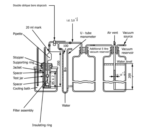
Figure 1. Diagram of a Manual CFPP Apparatus
Test Jar_ cylindrical, of clear glass, flat bottom, 33.2 to 34.8-mm outside diameter, and 115 to 125 mm in height. The inside diameter of the jar can range from 30.0 to 32.4 mm, within the constraint that the wall thickness be no greater than 1.6 mm. The jar shall have a line to indicate a sample height 54 ± 3 mm above the inside bottom. See Fig. 1.
Thermometers_ having the following ranges and conforming to the requirements prescribed in Specification E 1 for thermometers:
| Temperature | Thermometer Number | ||
| Thermometer | Range | ASTM | IP |
| High range for CFPP to -30 °C | −38 to +50°C | 5C | 1C |
| Low range for CFPP below -30 °C | −80 to +20°C | 6C | 2C |
| Cooling Bath | -80 to +20°C | 61C | 63C |
Digital contact thermometer requirements:
Parameter Requirement
DCT Guide E2877 Class F or better
Nominal Temperature Range –38 °C to +50 °C for CFPP down to –30 °C
–80 °C to +20 °C for CFPP below –30 °C
–80 °C to +20 °C for cooling bath
Display Resolution 0.1 °C, minimum
Accuracy ±500 mK (±0.5 °C) for combined probe and sensor
Sensor Type Platinum Resistance Thermometer (PRT)
Sensor Sheath 4.2 mm OD maximum
Sensor Length Less than 10 mm
Immersion Depth Less than 40 mm per Practice D7962.
Measurement Drift Less than 500 mK (0.5 °C) per year.
Response Time Less than or equal to 4 s
Calibration Error Less than 500 mK (0.5 °C) over the range of use.
Calibration Range Consistent with temperature range of use
Calibration Data Four data points evenly distributed over the calibration range that is consistent with the range of use. The calibration data is to be included in calibration report.
Calibration Report From a calibration laboratory with demonstrated competency in temperature calibration which is traceable to a national calibration laboratory or metrology standards body.
Cork_ to fit the test jar, bored centrally for the test thermometer.
Jacket_ watertight, cylindrical, metal, flat-bottomed, 115 6 3-mm depth, with inside diameter of 44.2 to 45.8 mm. It shall be supported in a vertical position in the cooling bath (see description of baths below) so that not more than 25 mm projects out of the cooling medium, and shall be capable of being cleaned.
Disk, cork or felt_ 6 mm thick to fit loosely inside the jacket.
Gasket_ to fit snugly around the outside of the test jar and loosely inside the jacket. The gasket may be made of rubber, leather, or other material that is elastic enough to cling to the test jar and hard enough to hold its shape. Its purpose is to prevent the test jar from touching the jacket.
Baths_ maintained at prescribed temperatures with a firm support to hold the jacket vertical. The required bath temperatures may be obtained by refrigeration if available, otherwise by suitable freezing mixtures. Freezing mixtures commonly used for temperatures down to those shown are as follows:
For Temperatures Down
Ice and water 9°C
Crushed ice and sodium chloride crystals −12°C
Crushed ice and calcium chloride crystals −27°C
Acetone or petroleum naphtha
(see Section on Reagents and Materials D97)
chilled in a covered metal beaker with an ice-salt
mixture to −12°C then with enough solid carbon dioxide
to give the desired temperature. −57°C
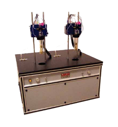
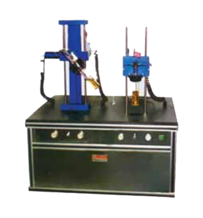
There are many manufacturers of these cold properties instruments in many cases combined with cloud point D2500, D7689, Pour Point of Crude Oils D5853 among others. Figure 2 below shows a typical semiautomatic arrangement of these instruments from Nordexp and an automatic version from Tanaka in fig. 3.
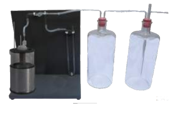
Figure 2. Typical Semiautomatic Apparatus for D6371 CFPP testing
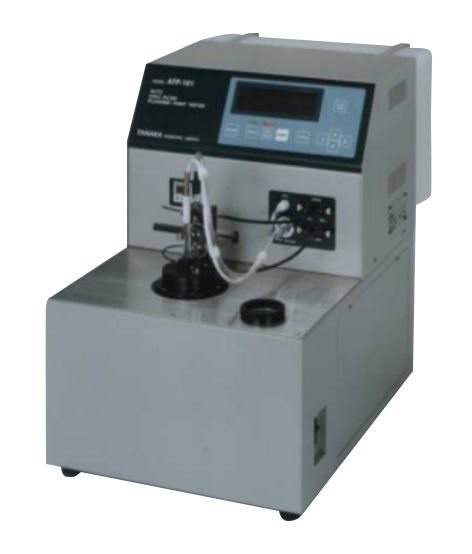
Figure 3. Automatic Tanaka CFPP Tester
Reagents and Materials
Heptane, clean commercial or reagent grade.
(Warning—Flammable. Harmful if inhaled.)
Acetone, clean commercial or reagent grade.
(Warning—Extremely flammable.)
Filter Paper, (approximately 4 µm to 6 µm retention).
Certified Reference Materials (CRM).
Sampling
Unless otherwise specified in the commodity specification, samples shall be taken as described in Practice D4057 or D4177 in accordance with the requirements of national standards or regulation for the sampling of the product under test, or both.
Preparation of Test Specimen
Filter approximately 50 mL of the sample (see 8.1 of D6371) at laboratory ambient temperature, but in any case, not at a temperature less than 15 °C, through dry filter paper (see 7.3 in D6371).
Preparation of Apparatus
Prepare the manual apparatus or the automated apparatus for operation in accordance with the manufacturer’s instructions for calibrating, checking, and operating the equipment. See Fig. 1 for manual apparatus.
Before each test, dismantle the filter unit and wash the pieces and the test jar, the pipet and the thermometer with heptane, then rinse with acetone and dry in a stream of filtered air. Check the cleanliness and dryness of all elements, including the jacket. Examine the wire mesh and the joints for damage; if necessary, renew them.
Check that the screw cap (see Apparatus section D6371) is tight enough to prevent leakage. FCollow carefully instructions in D6371.
Calibration and Standardization
Adjust the automated CFPP apparatus (when used) in accordance with the manufacturer’s instructions.
Calibrate the temperature measuring device in accordance with the manufacturer’s instructions.
Periodically verify the correct functioning of manual and automated apparatus using a certified reference material or in-house secondary reference material, such as fuel of known CFPP value. NOTE—It is preferable that verification be carried out at least two times a year, where possible, using certified reference materials. The apparatus should be checked more frequently (for example, weekly) using a secondary verification material.
When the CFPP values obtained using a verification material deviate by more than the test repeatability (see 14.2 in D6371), or an unacceptable statistical quality control bias is observed, check the condition and operation of the apparatus to ensure conformity with the specification as stated in this test method. The manufacturer’s instruction manual should provide guidance on ensuring that the apparatus is correctly set up and calibrated.
Procedure
Manual Apparatus:
Establish the cooling bath temperature at –34 °C 6 0.5 °C.
Place the insulating ring on the bottom of the jacket. If spacers are not mounted on the insulating ring, position them approximately 15 mm and 75 mm above the bottom of the test jar.
Pour the filtered specimen into the clean and dry test jar to the mark (45 mL).
Close the test jar with the stopper carrying the pipet with filter unit and the appropriate thermometer (see Apparatus Section for details). Use a low-range thermometer if the expected CFPP is below –30 °C. Thermometers shall not be changed during the test. Adjust the apparatus in such a way that the bottom of the filter unit rests on the bottom of the test jar, and position the thermometer so that its lower end is 1.5 mm ± 0.2 mm above the bottom of the test jar. Take care to ensure that no part of the thermometer is not in contact with the side of the test jar or the filter body.
NOTE—The precise positioning of the thermometer in the test jar is a critical parameter of this test method. The position of the lower end of the thermometer above the bottom of the test jar can be indirectly measured by marking the stem of the thermometer flush with the stopper when the lower end of the thermometer is just touching the bottom of the test jar, and then pulling the thermometer up such that the reference line is 1.5 mm ± 0.2 mm above the top of the stopper.
Continue as described in section 12 of D6371 for manual and automated analyzers.
Report
Report the temperature read or indicated at the beginning of the last filtration to the nearest 1 °C as the CFPP.
If the specimen has reached −51 °C without plugging report as “Not plugged at −51 °C.”
The report shall contain at least the following information:
The type and identification of the product under test;
A reference to this test method;
The sampling procedure used (see Section 8 of D6371));
The result of the test (as per 13.1 or 13.2 of D6371);
Any deviation from the procedure described (see Note 9 and Note 11 of D6371); and
The date of the test.
Precision and Bias
The precision of this procedure as determined by the statistical examination of the interlaboratory test results using liquid-in-glass thermometers is as follows:
Repeatability—The difference between results obtained on the same day by the same operator with the same apparatus under constant operating conditions on identical test material, would in the long run, with normal and correct operation of the test method, exceed 1.76 °C only in one case in twenty.
Reproducibility—The difference between two single and independent results obtained by different operators working in different laboratories on identical test material, would in the long run, in the normal and correct operation of the test method, exceed the values indicated by the formula:
0.102 (25−X) °C
where: X is the average of the two results being compared, only in one case in twenty.
NOTE—The interlaboratory test program used to determine the precision of this test method was carried out in 1988 by the IP. The program involved 46 laboratories and 5 samples, ranging in CFPP values from 0 °C to −33 °C. Extrapolations to measurements more than a few degrees outside this range are unsupported by the data. The raw data from the 1988 program was reanalyzed in 1997 using the ASTM D2PP program. The report of the reevaluation is available from ASTM Headquarters (See Research Report RR:D02-1452).
Bias— The procedure in this test method has no bias because the value of CFPP can be defined only in terms of a test method.
Relative Bias—The current interlaboratory tests confirm that there is no relative bias between the manual and automated apparatuses. Both apparatuses are suitable for reference purposes.