ISO 4406
Hydraulic fluid power – Fluids – Method for coding the level of contamination by solid particles
In an attempt to avoid serious operational problems in machinery and hydraulic fluid power equipment ISO 4406 test method is used to count and measure the size of dispersed Solid Particle Contaminants, always present in hydraulic fluids, in the overall range from 4 µm to or larger than 15 µm. ISO 4406 uses Automatic Particle Counter (APC) and microscope sizing and counting.
A reliable determination of size and particle distribution in hydraulic fluids and other products constitutes a valuable tool not only to more precisely determine the product specifications but also to monitor fuels and in-service oils and optimize preventive maintenance programs of engines and machinery reducing downtime and repair costs avoiding unnecessary unscheduled costly repairs. Particles can shorten the lifetime of fuel systems components, fuel pumps, injectors and other devices.
Particle counts are affected by a variety of factors. These factors include procurement of sample, particle counting accuracy and the sample container (where used), and its cleanliness. Proper care should be taken during sample procurement to ensure that the sample obtained is representative of the fluid circulating in the system.
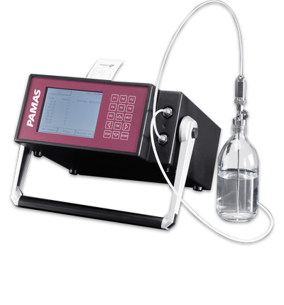
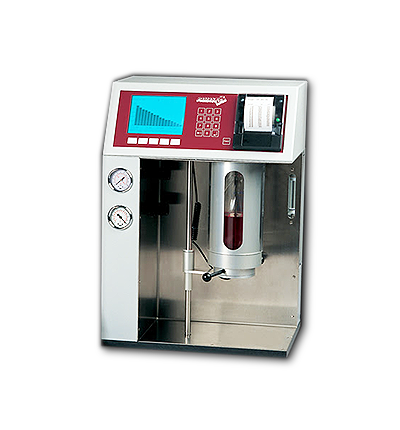
The optical PAMAS particle counters exceed the requirements of common cleanliness standards and provide a detailed particle size distribution for up to 32 size areas. The measuring result of an optical particle counter includes as well important ranges that are not covered by International standards such as ASTM, ISO and SAE among others.
Normative References
ISO 4406 Standards:
ISO 4407 Hydraulic Fluid Power- Fluid Contamination- Determination of particulate contamination by the counting method using an optical microscope
ISO 11171 Hydraulic Fluid Power- Calculation of Automatic Particle Counter for Liquids
ISO 11500, Hydraulic fluid power – Determination of the particulate contamination level of a liquid sample by automatic particle counting using the light-extinction principle
Terminology
Definitions of Terms Specific to This Standard:
particles, n—solid particles and dispersed water droplets which are detected and counted by this test method.
particle count, n—the sum of the number of solid particles and dispersed water droplets.
particle size, µm(c), n—the projected area equivalent diameter of spherical particles passing through the detecting cell in accordance with ISO 11171.
particle size cumulative count, n—the total number of particles per mL, in size bands, ≥4 µm(c), ≥6 µm(c), and ≥14 µm(c),
Discussion—Automatic particle counters may also count the total number of particles per mL, in size bands, in addition to those up to ≥100 µm.
ISO Codes, n—a standard method for coding the level of contamination by particles.
Discussion—Results are expressed by ISO Codes as specified by ISO 4406. These codes are written in the form of x/y/z, where x, y and z are ISO Codes equivalent to the cumulative counts, per mL, for particle size bands ≥4 µm(c), ≥6 µm(c), and ≥14 µm(c) respectively.
NOTE 5—All particle counts are per milliliter.
coincidence error limit, n—the highest concentration of ISO ultrafine test dust (ISO 12103-A1 or ISO UFTD) that can be counted with an automatic particle counter with less than 5 % error resulting from the presence of more than one particle in the sensor/laser optical path at a time.
test specimen, n—an aliquot of the test sample.
Summary of Test Method
The original code, in accordance with the first edition of this document, stated the reporting at two sizes ≥ 5 µm and ≥ 15 µm. The sizes in this document account for the use of a different calibration standard for optical automatic particle counters (APCs). The reported sizes are ≥ 4 µm(c), ≥ 6 µm(c) and ≥ 14 µm(c), the last two of these being equivalent to the 5 µm and 15 µm particle sizes obtained using the ISO 4402:19911) method of calibrating APCs. Throughout this document the use of µm(c) means that particle size measurements are carried out using an automatic particle counter that has been calibrated in accordance with ISO 11171.
Measurement of particles using an optical microscope as specified in ISO 4407 establishes the size of a particle as being equal to its longest dimension, whereas an automatic particle counter derives the size of an equivalent particle from its cross-sectional area, a value different in most cases from that determined with a microscope. The particle size to be reported for measurements by microscope 5 m and 15m are unchanged from those specified in the first edition of ISO 4406.
Apparatus
Automatic Particle Counter (APC) —Operating on the laser light obscuration principle, comprising an optical measurement cell, bi-directional double pump, electronics and software to analyze the test specimen, and display and print the particle measurement data.
Test Specimen Container, cylindrical, made of glass or other suitable material, of at least 125 mL volume with provision for holding the test specimen input tube at least 10 mm above the bottom of the container, and a cap with a suitable inert internal seal.
NOTE 6—It is recommended that glass test specimen containers should be used to avoid any potential problems with particles adhering to the insides of the containers due to static electricity that could occur with some samples or some specimen containers.
Waste Container, for collecting the tested test specimen.
Filter Apparatus, general purpose for filtering heptane or other solvents.
Filters, cellulose, glass fiber or polycarbonate 0.45 µm. Printer, to record details of the measurements and results.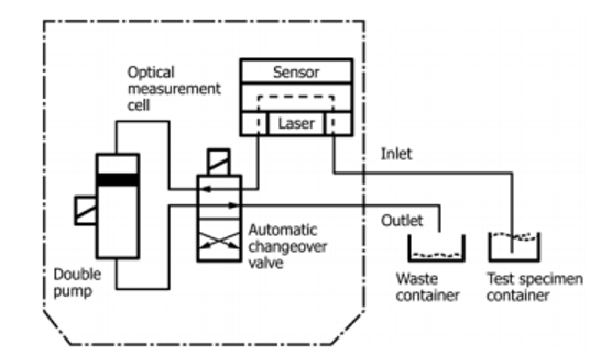
Figure 1. Schematics of an Automatic Particle Counter
Apparatus Verification and Calibration
Verification:
Follow the manufacturer’s instructions to prepare the verification fluid.
Verify the correct operation of the APC at least every 6 months or more frequently if required by local quality controls, by using the verification fluid. The result obtained shall be equal to or less than R/√2 of the measurement plus the uncertainty of the verification fluid, from the certified ≥4 µm(c) value of the verification fluid, where R is the reproducibility of the test. If the result obtained is not within this figure, ensure the sample preparation is in accordance with the manufacturer’s instructions, check the verification fluid’s validity date, and run a further test using the filtered heptane to confirm that the inlet tube and cell assembly are free from contaminants. Then repeat the verification. If the result is still not within the allowed tolerance, contact the manufacturer.
Calibration:
The APC shall be calibrated according to ISO 11171 at least every 12 months or more frequently if required by local quality controls or by the manufacturer.
Follow the manufacturer’s instructions regarding factory calibration or on-site calibration using integral auto, self checking, calibration software.
The test specimen flow rate through the measurement cell shall be the same for calibration, verification and testing.
After calibration, verify the correct operation of the APC in accordance with ISO 11500.
Procedure
Before commencing a test, gently shake the test specimen, for a minimum of 1 min and then allow approximately 60 s before immediately starting the test. If the test is not started within approximately 90 s after shaking, gently re-shake the test specimen for a further minute.
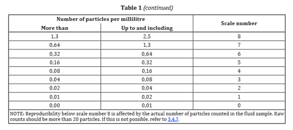
The code for contamination levels using automatic particle counters comprises three scale numbers that permit the differentiation of the dimension and the distribution of the particles as follows:
— the first scale number represents the number of particles equal to or larger than 4 µm(c) per milliliter of fluid;
— the second scale number represents the number of particles equal to or larger than 6 µm(c) per milliliter of fluid;
— the third scale number represents the number of particles equal to or larger than 14 µm(c) per milliliter of fluid. The code for microscope counting comprises two scale numbers using 5 µm and 15 µm.
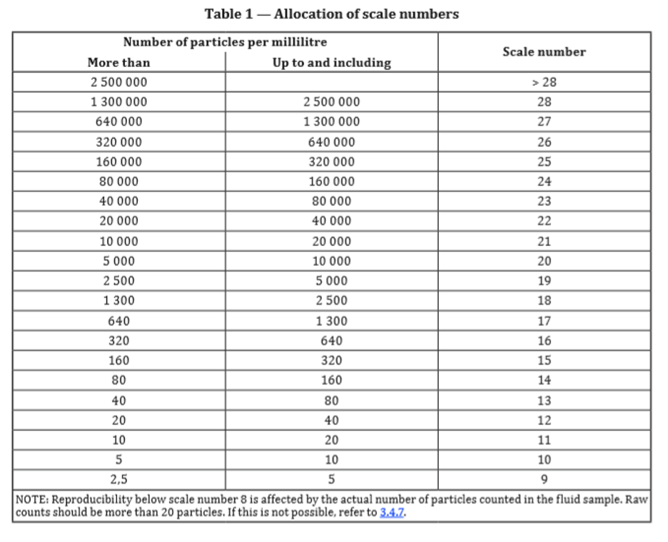
The scale numbers are allocated according to the number of particles counted per milliliter of the fluid sample (see Table 1).
A step ratio of generally two, as given between the upper and lower limits for the number of particles per milliliter in Table 1, has been adopted to keep the number of scale numbers within a reasonable limit and to ensure that each step is meaningful.
Determination of code using automatic particle counter analysis
Counting shall be undertaken in accordance with ISO 11500 or another recognized method, using an APC calibrated to ISO 11171.
– A scale number shall be allocated to the number of particles equal to or larger than 4 µm(c).
– A second scale number shall be allocated to the number of particles equal to or larger than 6 µm(c).
– A third scale number shall be allocated to the number of particles equal to or larger than 14 µm(c).
– The three numbers shall be written one after the other and separated by oblique strokes (slashes).
EXAMPLE A code of 22/18/13 signifies that there are more than 20 000 and up to and including 40 000 particles equal to or larger than 4 µm(c), more than 1 300 and up to and including 2 500 particles equal to or larger than 6 µm(c) and more than 40 and up to and including 80 particles equal to or larger than 14 µm(c) in 1 ml of a given fluid sample.
Graphical presentation of ISO Code results shall be as described below.
When applicable, include either “*” (too numerous to count) or “—” (no requirement to count) notation when reporting the scale number.
EXAMPLE 1 */19/14 means that this sample has too many particles equal to or larger than 4 µm(c) to count.
EXAMPLE 2 —/19/14 means that there was no requirement to count particles equal to or larger than 4 µm(c).
When the raw data in one of the size ranges results in a particle count of fewer than 20 particles, the scale number for that size range shall be labelled with the symbol ≥.
EXAMPLE A code of 14/12/≥7 signifies that there are more than 80 and up to and including 160 particles equal to or larger than 4 µm(c) per milliliter and more than 20 and up to and including 40 particles equal to or larger than 6 µm(c) per milliliter. The third part of the code, ≥7, indicates that there are more than 0,64 and up to and including 1,3 particles equal to or larger than 14 µm(c) per milliliter but less than 20 particles were counted which lowers statistical confidence. Because of this lower confidence, the 14 µm (c) part of the code can be higher than 7, indicating a particle count of more than 1.3 particles per milliliter.
Determination of code using microscope sizing
- Counting shall be undertaken in accordance with ISO 4407.
- A scale number shall be allocated to the number of particles equal to or larger than 5 µm.
- A second scale number shall be allocated to the number of particles equal to or larger than 15 µm.
- In order to relate to counts obtained with an automatic particle counter, the code shall be stated in three-part form with the first part given as “—”.
EXAMPLE —/18/13.
Graphical presentation of ISO Code results shall be as described below.
Identification statement (reference to this document) Use the following statement in test reports, catalogues and sales literature when electing to comply with this document:
“Solid contaminant code conforms to ISO 4406, Hydraulic fluid power — Fluids — Method for coding the level of contamination by solid particles.”
Graphical presentations of the code number
For automatic particle counter analysis, report the contaminant code by:
– Allocating a first scale number to the total number of particles equal to o larger than 4 µm(c).
– Allocating a second scale number to the total number of particles equal to or larger than 6 µm(c).
– Allocating a third scale number to the total number of particles equal to or larger than 14 µm(c).
– Writing these three numbers separated by oblique strokes. See for example 22/18/13 in Fig. 2.
For analysis by microscope, use “_” in place of the first scale number and allocate the second and third numbers based upon the counts at 5 µm and 15 µm respectively.
Interpolation is acceptable. Extrapolation is not permissible.
In cases of dispute also report the instrument model used and software version installed.
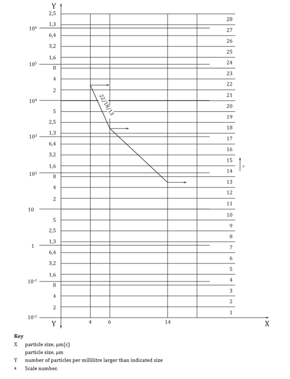
Figure 2. Typical graphical representation of ISO code results