ASTM D5002-19
Standard Test Method for Density, Relative Density, and API Gravity of Crude Oils by Digital Density Analyzer
ASTM Standard Test Method D5002 covers the determination of density, relative density and API Gravity of crude oils that can be handled in a normal fashion as liquids at test temperatures between 15 °C and 35 °C utilizing either manual or automated sample injection equipment. This test method for the density of oils applies to crude oils with high vapor pressures provided appropriate precautions are taken to prevent vapor loss during transfer of the sample to the density analyzer. This test method was evaluated in round robin testing using crude oils in the 0.75 g ⁄mL to 0.95 g ⁄mL range. Lighter crude oil can require special handling to prevent vapor losses. Heavier crudes can require measurements at higher temperatures to eliminate air bubbles in the sample. The accepted units of measurement of density are grams per millilitre and kilograms per cubic metre.
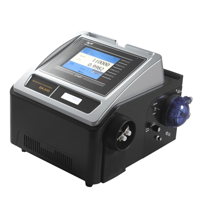
“The Density Meter DA-650 from Kyoto Electronics Manufacturing KEM, is a fast instrument capable of measuring density in only 20 s with a minimal sample of 1.0 mL, designed for all the product line to determine density, relative density and API gravity in full compliance to ASTM D5002 standard test method. Based on a state-of-the-art temperature-controlled U-tube and automatic viscosity correction for high viscosity samples with a precision of 0.00002 g/cm3, which will definitely expand the horizon of fuel, petroleum and petrochemical products characterization.”
The whole product line of KEM density meters correlates with all density standard test methods ASTM D1250, D1475, D4052, D4808, D5798, D5931 and ISO standards 12185 and 15212”.
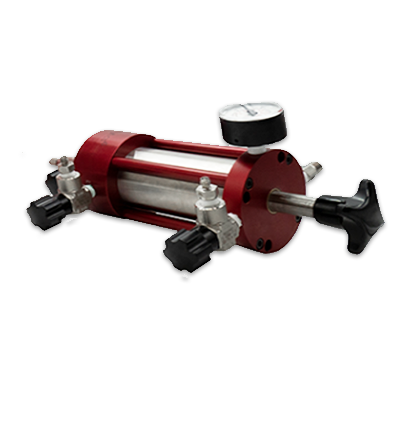
To preserve the integrity of the samples it is advisable to use Manual Piston Cylinders especially in case of live crudes. Measurements like density and vapor pressure require the use of a pressurized sampling system to avoid loss of volatile and gaseous components.
Referenced Documents
ASTM Standards:
D287 Standard Test Method for API Gravity of Crude Petroleum and Petroleum Products (Hydrometer Method)
D941 Standard Test Method for Density and Relative Density (Specific Gravity) of Liquids by Lipkin Bicapillary Pycnometer
D1193 Specification for Reagent Water
D1217 Standard Test Method for Density, Relative Density (Specific Gravity) of Liquids by Bingham Pycnometer
D1250 Guide for Use of Petroleum Measurement Tables
D1298 Standard Test Method for Density, Relative Density or API Gravity of Crude Petroleum and Liquid Petroleum Products by Hydrometer Method
D4052 Standard Test Method for Density, Relative Density and API Gravity of Liquids by Digital Density Meter
D4057 Practice for Manual Sampling of Petroleum and Petroleum Products
D4177 Practice for Automatic Sampling of Petroleum and Petroleum Products
D4377 Standard Test Method for Water in Crude Oils by Potentiometric Karl Fischer Titration
Terminology
Definitions:
ldensity, n—mass per unit volume at a specified temperature.
Discussion—The SI unit of density is kg/m3 ; the unit of measure g/cm3 is commonly used in industry. Less preferred units, for example, kg/L or g/mL, are still in use.
relative density, n—the ratio of the density of a material at a stated temperature to the density of water at a stated temperature.
Discussion—Relative density historically known as “specific gravity”. Commonly used stated temperatures are 20 °C ⁄20 °C, 15 °C ⁄15 °C, 20 °C ⁄4 °C and 60 °F ⁄60 °F.
Definitions of Terms Specific to This Standard:
API gravity, n—a special function of relative density 60 °F ⁄60 °F, represented by:
°API = 141.5 /relative density – 131.5 (1)
Discussion—No statement of reference temperature is required since 60 °F is included in the definition.
Summary of Test Method
Approximately 1 mL – 2 mL of crude oil sample is introduced into an oscillating sample tube and the change in oscillating frequency caused by the change in the mass of the tube is used in conjunction with calibration data to determine the density, relative density, and API gravity of the sample. Both manual and automated injection techniques are described.
Significance and Use
Density is a fundamental physical property that can be used in conjunction with other properties to characterize the quality of crude oils. The density or relative density of crude oils is used for the conversion of measured volumes to volumes at the standard temperatures of 15 °C or 60 °F and for the conversion of crude mass measurements into volume units.
The application of the density result obtained from this test method, for fiscal or custody transfer accounting calculations, can require measurements of the water and sediment contents obtained on similar specimens of the crude oil parcel.
Determination of the density or relative density of petroleum and its products by the dedicated density meters shown in the Apparatus section is necessary for the conversion of measured volumes to weights and to volumes at the standard temperature of 15 °C.
Apparatus
A built-in digital analyzer consisting of a U-shaped, oscillating tube, and a system for electronic excitation, frequency counting, and display. The analyzer shall accommodate the accurate measurement of the sample temperature during measurement or shall control and keep the sample temperature constant to 60.05 °C. The instrument shall be capable of meeting the precision requirements described in this test method.
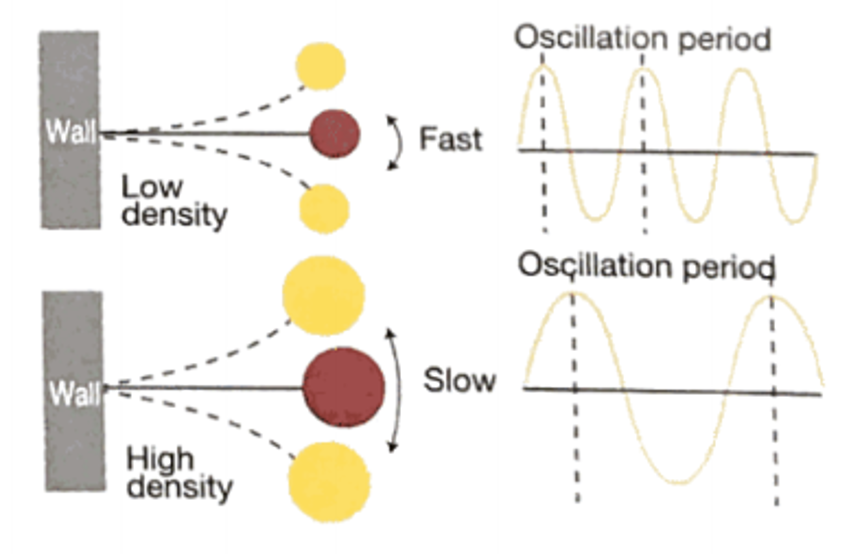
The weight of sample will vibrate in the oscillating U-tube and the measured oscillating period is specific to a substance in proportion to its mass of weight. By this means and since the volume is constant it is possible to determine the density of a substance by measuring the oscillating period.
The bench top KEM DA -650 series determines density in 20 seconds with an accuracy of up to 0.000001 g/cm3.
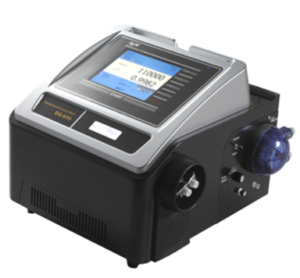

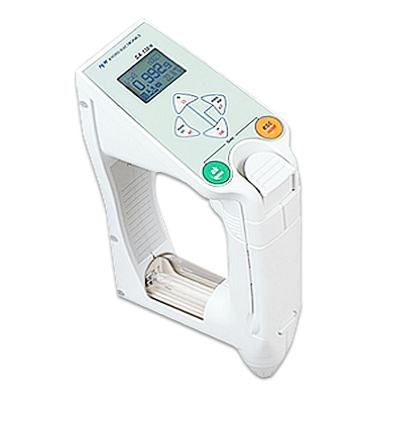
Bench Top DA-650 and Portable DA-130N KEM Density/Specific Gravity Meters
The portable density meter DA-130N measures the density in the 0 to 2 g/cm3 with an accuracy of ±0.001 g/cm3.
Preparation of Apparatus
Set up the density analyzer and constant temperature bath following the manufacturer’s instructions.Adjust the bath or internal temperature control so that the desired test temperature is established and maintained in the sample compartment of the analyzer. Calibrate the instrument at the same temperature at which the density of the sample is to be measured.
Calibration of Apparatus
Calibrate the instrument when first setting up and whenever the test temperature is changed. Thereafter, conduct calibration checks at least weekly during routine operation or more frequently as may be dictated by the nature of the crude oils being measured.
Initial calibration, or calibration after a change in test temperature, necessitates calculation of the values of the Constants A and B from the periods of oscillation, (T), observed when the sample cell contains certified reference liquids such as air and freshly boiled reagent water. Other calibrating materials such as n-nonane, n-tridecane, cyclohexane, and n-hexadecane (for high temperature applications) can also be used as appropriate.
While monitoring the oscillator period, T, flush the sample tube with petroleum naphtha, followed with an acetone flush and dry with dry air. Continue drying until the display exhibits a steady reading. In cases where saline components can be deposited in the cell, flush with distilled water followed by acetone and dry air. Contaminated or humid air can affect the calibration. When these conditions exist in the laboratory, pass the air used for calibration through a suitable purification and drying train. In addition, the inlet and outlet ports for the U-tube must be plugged during measurement of the calibration air to prevent ingress of moist air.
Allow the dry air in the U-tube to come to thermal equilibrium with the test temperature and record the T-value for air.
Introduce a small volume, about 1 mL to 2 mL, of freshly boiled reagent water into the sample tube using a suitable syringe. The water must be free of even the smallest air or gas bubbles. The sample tube shall be completely full. Allow the water to reach thermal equilibrium at the test temperature and record the T-value for water and the test temperature.
Alternatively introduce one of the hydrocarbon calibration standards and measure the T-value as in D5002 (10.2.3).
Calculate the density of air at the temperature of test using the following equation:
ρa = 0.001293 [273.15/T[P/101.325] g/mL (2)
where: ρa = density of air,
T = temperature, K, and
P = barometric pressure, kPa.
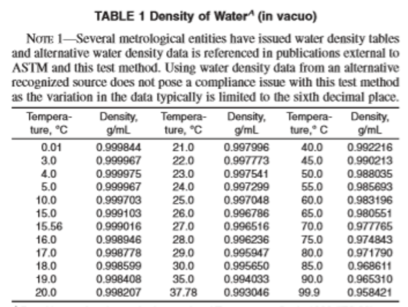
Determine the density of water at the temperature of test by reference to Table 1.
Alternatively record the density at the test temperature for the hydrocarbon calibrant used in D5002(10.2.4) as obtained from an appropriate reference source or from direct determination (see Reagents & Materials Section).
Using the observed T-values and the reference values for water and air, calculate the values of the Constants A and B using the following equations:
A = [T2w – T 2a]/[ρw – ρa] (3)
B = T2a – (A x ρa) (4)
where:
Tw = observed period of oscillation for cell containing water, µs,
Ta = observed period of oscillation for cell containing air, µs,
ρw = density of water at test temperature, g/mL, and
ρa = density of air at test temperature, g/mL.
Alternatively, use the T and d values for the other reference liquid if one is used.
If the instrument is equipped to calculate density from the Constants A and B and the observed T-value from the sample, then enter the constants in the instrument memory in accordance with the manufacturer’s instructions.
Check the calibration and adjust if needed by performing the routine calibration check described in D5002(10.3).
To calibrate the instrument to determine relative density, that is, the density of the sample at a given temperature referred to the density of water at the same temperature, follow D5002(10.2.1 – 10.2.9), but substitute 1.000 for ρw in performing the calculations described in D5002(10.2.8).
Since some crude oils can be difficult to remove from the sample tube, frequent calibration checks are recommended. These checks and any subsequent adjustments to Constants A and B can be made if required, without repeating the calculation procedure.
NOTE 2—The need for a change in calibration is generally attributable to deposits in the sample tube that are not removed by the routine flushing procedure. Although this condition can be compensated for by adjusting A and B, as described below, it is good practice to clean the tube with warm chromic acid solution (Warning—Causes severe burns. A recognized carcinogen.) whenever a major adjustment is required. Chromic acid solution is the most effective cleaning agent; however, surfactant-type cleaning fluids have also been used successfully.
Flush and dry the sample tube as described earlier and allow the display to reach a steady reading. If the display does not exhibit the correct T-value or density for air at the temperature of test, repeat the cleaning procedure or adjust the value of Constant B commencing with the last decimal place until the correct density is displayed.
If adjustment to Constant B was necessary then continue the recalibration by introducing freshly boiled reagent water into the sample tube as described and allowing the display to reach a steady reading. (See Warning note in D5002 7.3.) If the instrument has been calibrated to display the density, adjust the reading to the correct value for water at the test temperature (see Table 1) below by changing the value of Constant A, commencing with the last decimal place. If the instrument has been calibrated to display the relative density, adjust the reading to the value 1.0000.
NOTE 3—In applying this periodic calibration procedure, it has been found that more than one value each for A and B, differing in the fourth decimal place, will yield the correct reading for the density of air and water. The setting chosen would then be dependent upon whether it was approached from a higher or lower value. The setting selected by this method could have the effect of altering the fourth place of the reading obtained for a sample.
Some analyzer models are designed to display the measured period of oscillation only (T-values) and their calibration requires the determination of an instrument constant K, that must be used to calculate the density or relative density from the observed data. Use the procedure in D5502 (10.4.1, 10.4.2, and 10.4.3) in this case.
Flush and dry the sample tube as described in 10.2.1 and allow the air to reach equilibrium at the test temperature and the readout to display a steady value. Record the T-value for air.
Introduce a small volume, 1 mL to 2 mL, of freshly boiled reagent water, allow the display to reach a steady reading and record the T -value for water.
Using the observed T-values and the reference values for water and air D5002(10.2.5 and 10.2.6), calculate the instrument constant, K, using the following equations:
for density:
K1 = [ρ2w – ρa]/[T2w – T2a ] (5)
for relative density:
K2 = [1.0000 – ρa]/[T2w – T2a ] (6)
where: Tw = observed period of oscillation for cell containing water, µs,
Ta = observed period of oscillation for cell containing air, µs,
ρw = density of water at test temperature, g/mL, and
ρa = density of air at test temperature, g/mL.
Procedure
Introduce about 1 mL to 2 mL of crude oil into the clean, dry, sample tube of the instrument using a suitable syringe. Leave the syringe in place and plug the exit port.
Ensure that the sample tube is properly filled and that no gas bubbles are present. The sample shall be homogeneous and free of even the smallest gas bubbles. Check the integrity of the filled sample by using optical or physical methods to verify absence of gas bubbles. If gas bubbles are detected, empty and refill the sample tube, and recheck for gas bubbles.
Allow the sample to equilibrate to the test temperature before proceeding to evaluate the test sample for the presence of unseen air or gas bubbles.
For dark crude oil samples the observation of air or gas bubbles in the sample tube is very difficult. The presence of bubbles can often be detected, however, by observing the fluctuations of the digital display of the T-value or density value. Air or gas bubbles cause large random variations in the third and fourth significant figures for density reading and fifth and sixth significant figures for T readings. When bubbles are absent and the sample is at equilibrium with the test temperature, the displayed values are stable, do not drift, and show only small variations of the order of ± 1 to 2 units in the last significant figure. If stable values are not observed after a few minutes, then repeat the injection of a new sample into the tube.
NOTE 4—When viscous liquids are being measured, a stable reading can be achieved even when air or gas bubbles are present. Careful injection of fresh sample will often eliminate bubbles. Since bubbles contribute to lower density readings, an observed increase in the density of the liquid after injection of fresh sample tends to suggest that bubbles were previously present.
After the instrument displays a steady reading to four significant figures for density, relative density, and API gravity, and five for T-values, indicating that temperature equilibrium has been reached, record the density, relative density, and API gravity or T-value.
Flush and dry the sample tube and check the calibration as described in previously prior to introducing another sample.
Automated Injection:
The use of an autosampler (see Apparatus Section) is required when analyzing samples by automated injection. Follow manufacturer’s instructions for ensuring the integrity of the test specimen prior to analysis, as well as for transferring a representative test specimen into the instrument for analysis.
When using an autosampler for samples expected or known to contain high quantities of volatile components, use two separate test specimens per sample, in order that errors due to potential sample handling of volatile materials and potential gas bubble formation may be detected and the system performance monitored. For all other samples, a single determination using an autosampler is sufficient.
If the lab decides to perform a second automated injection determination for a given sample, the differences between each determination should not exceed a determinability criterion determined by a series of tests on a representative crude sample and which assures that the repeatability performance of Table 2 is met. Averaged results meeting the necessary acceptance criteria are to be used for reporting purposes.
If the two determinations fall outside this acceptance criteria, both determinations are to be discarded and injection shall be repeated until the acceptance criteria identified in the previous sentence is satisfied. In cases where the acceptance criteria is not initially satisfied, the lab may need to investigate and take corrective actions before proceeding with subsequent analyses.
Record the density, relative density, and API Gravity results, or a combination thereof, determined by the analyses as appropriate, such as by using the instrument print out of results to meet the recording requirements.
The injection of the sample in the dedicated density meters occurs either manually by means of a syringe or automatically by a built in pump according to the KEM Operation Manual and model. Automated or Manual Syringe Injection in all product lines takes precaution for sample integrity and bubbles absence as describied in D4052 Section 12 or Section 11 of D5002. Follow manufacturer’s instructions for ensuring the integrity of the test specimen prior to analysis, as well as transferring a representative test specimen into the instrument for analysis.
NOTE 5—Some digital density analyzers are equipped to automatically calculate and report sample results in API gravity units (see Test Method D287 or D1298), based on the density or relative density results, or a combination thereof, determined by this test method and using the appropriate conversion equation derived from Guide D1250 (which excludes the glass expansion factor), for the specific sample type being analyzed.
Calculations
Calculating Density Analyzers—The recorded value is the final result, expressed either as density in g/mL, kg/m3 or as relative density or API gravity. Note that kg/ m3 = 1000 × g⁄mL.
Noncalculating Density Analyzers—Using the observed T-value for the sample and the T-value for water and appropriate instrument constants determined in the calibration section, calculate the density or relative density using Eq 7 and Eq 8. Carry out all calculations to six significant figures and round the final results to four. Note that kg/m3 = 1000 × g⁄mL.
for density:
density, g/mL at t = ρw + K1(T2s – T2w) (7)
for relative density:
relative density, t/t = 1 + K2(T2s – T2w) (8)
where:
Tw = observed period of oscillation for cell containing water,
Ts = observed period of oscillation for cell containing sample,
ρw = density of water at test temperature,
K1 = instrument constant for density,
K2 = instrument constant for relative density, and
t = temperature of test, °C.
If it is necessary to convert a result obtained using the density analyzer to an API gravity or a density or relative density at another temperature, Guide D1250 can be used only if the table values have not been corrected for the glass expansion factor.
Report
In reporting density, give the test temperature and the units, (for example: density at 20 °C = 0.8765 g⁄mL or 876.5 kg⁄m3 (in vacuum)). Report the final result to four significant figures.
In reporting relative density, give both the test temperature and the reference temperature, but no units, (for example: relative density, 15/15 °C = x.xxxx). Report the final result to four significant figures.
If reporting sample results in API gravity units, report the final results to the nearest 0.1° API.
Precision and Bias
The precision of this test method as obtained by statistical examination of interlaboratory test results at test temperatures of 15 °C and 20 °C is as follows:
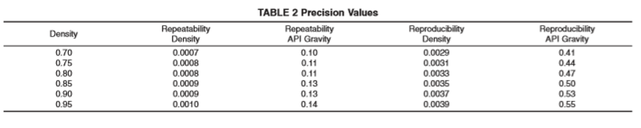
Repeatability—The difference between successive test results obtained by the same operator with the same apparatus under constant operating conditions on identical test material would, in the long run, in the normal and correct operation of this test method, exceed the following value only in 1 case in 20 (see Table 2):
range repeatability
0.75 to 0.95 0.00105X
where: X = sample mean.
Reproducibility—The difference between two single and independent results, obtained by different operators working in different laboratories on identical test material, would, in the long run, in the normal and correct operation of the test method, exceed the following values only in 1 case in 20 (see Table 2):
range reproducibility
0.75 to 0.95 0.00412X
where: X = sample mean.
Bias—After suggestions of its existence from (Fitzerald, H. & D “An assessment of Laboratory Density Meters” Petroleum Review, November 1992) a study has been performed which has confirmed the presence of a bias between known density values for reference materials and from values determined according to this test method on the same reference materials. The matrix for this bias study was comprised of 15 participants, each analyzing four reference oils with certified density values, established by the Netherlands Meet Instituut (NMI), by pycnometry, covering densities in the range of 747 kg⁄m3 to 927 kg⁄m3 at 20 °C, with viscosities between 1 mPa.s and 5000 mPa.s (also at 20 °C). Users should, therefore, be aware that results obtained by this test method can be biased by as much as 0.6 kg⁄m3 (0.0006 g⁄mL).
Keywords
API gravity; crude oils; density; digital density analyzer; relative density